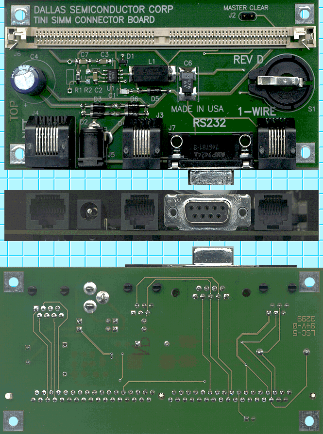
The image below is a composite image of the top, edge, and bottom of the TINI Socket with voltage regulator. These images were produced by placing the TINI Socket directly on the scanner glass and scanning at 150 DPI. The top and edge images do not appear as wide as the bottom image because the printed circuit board was farther from the glass (because the socket assemby was resting on the tops of the connectors). The white, horizontal connector is the SIMM socket into which the TINI Board is inserted. Pin 1 is the furthest to the right. The round connector on the right hand side of the top image is an iButton clip. The connectors along the edge of the board are summarized in the table below.
| Connector Purpose |
Ethernet |
Power |
Serial |
Serial |
1-Wire |
| Connector Type |
RJ-45 |
??? |
RJ-11 |
DB-9 |
RJ-11 |
The iButton clip accepts an F5 MicroCan iButton (such as the DS1921 Thermochron) easily, but it is a tight fit and put a nice scratch on the back of the iButton upon removal. Removing an F5 MicroCan iButton is not going to happen accidentally. We found the iButton much easier to remove with the snap-in fob attached to it, using the fob as a sort of iButton wrench. We do not have any of the thinner iButtons, so we can't comment on how those fit, but presumably they will work as well and may even come out with less effort (though still not accidentally).
We have found that inserting a small piece of heavy paper between the clip and the top of the iButton will prevent scratches when removing the iButton. The same technique can be used in reverse when inserting the iButton. Do not forget to remove the paper before attempting to use the device!
The power connector is a typical power connector type, but we don't know of any way to describe it other than verbosely. It is a round, coaxial connector that has an outside diameter of about 6 mm and an inside diameter of about 2 mm. These dimensions are different on the unregulated TINI Socket.
The TINI Socket has two RJ-11 connectors. One is a redundant serial interface hard-wired to the DB-9 serial connector. The other is a One Wire connector. The pins of the two RJ-11 connectors are numbered 1 through 6. As pictured, pin 1 is on the left (closest to the power connector) and pin 6 is on the right (furthest from the power connector). The pin-outs of the two RJ-11 connectors (serial and 1-Wire) are shown below.
As you can see from the image below, the two serial connectors are wired together. The serial connectors are wired as a DCE. That means that TINI transmits data on the Receive Data line and receives data on the Transmit Data line. Therefore, the cable used should be a regular modem cable (modems are also wired as DCEs). This is different from the so called null modem cable which is used to connect two DTEs (i.e. PC's). The pin-outs of the two serial connectors is shown here. Any pin tht is not shown has no connection. For the numbering of the RJ-11 pins, see The RJ-11 Connectors section.
|
Pin-outs of TINI Serial Connectors |
|||
|
RJ-11 Pin |
DB-9 Pin |
TINI Signal Name |
RS-232 Signal Name |
|
2 |
2 |
TX232 | RD (Receive Data) |
|
3 |
4 |
DTR232 | DTR (Data Terminal Ready) (See Note 1) |
|
4 |
5 |
Ground | SG (Signal Ground) |
|
5 |
3 |
RX232 | TD (Transmit Data) |
Note 1: DTR is used by the TINI board to reset the CPU. Therefore, if DTR is wired through to the device at the other end of the serial cable (e.g. a computer), that device can be used to reset TINI's CPU. Note that this may be both good and bad. It may be convenient to be able to reset TINI simply by toggling DTR, but if the other device toggles DTR at other times (e.g. when it reboots), then it may not be so desireable.
If it's called "one-wire", why do they need a six conductor connector for it? Using a six conductor connector allows power to be supplied through the other conductors. These pins may be used to power attached devices, but only you are responsible for what happens when you take excessive power from these "power" pins or introduce excessive noise into them. The pin-out of the one-wire connector is shown here. For the numbering of the RJ-11 pins, see The RJ-11 Connectors section.
|
Pin-out of TINI 1-Wire Connector |
|
|
RJ-11 Pin |
Signal Name |
|---|---|
|
1 |
VCC (5 volts regulated) |
|
2 |
Power Ground |
|
3 |
One Wire Data |
|
4 |
One Wire Ground |
|
5 |
No Connect |
|
6 |
V+ (unregulated DC) |
Connector J2, which is labeled "MASTER CLEAR", has one side connected to ground and the other side connected to pin 16 (INTOW) of the SIMM socket. INTOW is the INTernal One-Wire bus of the TINI board. According to the Dallas Semiconductor folks on the the TIN Mailing list, the internal 1-wire is used for four purposes:
b18<cr>f0<cr> from the loader prompt in JavaKit.